Keyboard and matrix
[keyboard]
[keyboard] section contains basic information of the keyboard, such as keyboard's name, chip, etc:
Supported chip and board
chip
- nrf52840
- nrf52833
- nrf52832
- nrf52811
- nrf52810
- esp32c3
- esp32c6
- esp32s3
- rp2040
- ALL stm32s supported by embassy-stm32 with USB
board
nice!nanonice!nano_v2pi_pico_wXIAO BLE
[matrix]
[matrix] section defines the physical key matrix IO information of the keyboard, aka input/output pins.
For split keyboard, this section should be just ignored, the matrix IO pins for split keyboard are defined in [split] section.
Key matrix
For the normal key matrix, in order to identify the IO pins take a look at your keyboard's schematic: The pin going to the diode (called anode) is an output pin, the pin coming out (called cathode) is an input pin:
Per default RMK assumes that your pins are col2row, meaning that the output pins (anodes) represent the columns and the input pins (cathodes) represent the rows. If your schemata shows the opposite you need to change the configuration to row2col
IO pins are represented with an array of string, the string value should be the GPIO peripheral name of the chip. For example, if you're using stm32h750xb, you can go to https://docs.embassy.dev/embassy-stm32/git/stm32h750xb/peripherals/index.html to get the valid GPIO peripheral name:
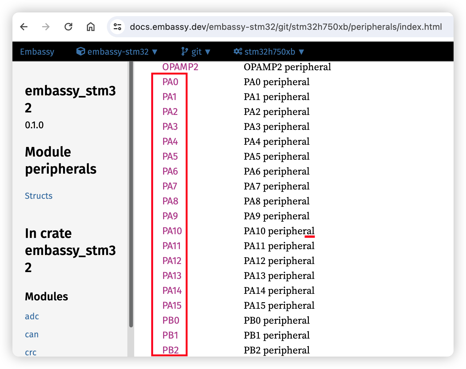
The GPIO peripheral name varies for different chips. For example, RP2040 has PIN_0, nRF52840 has P0_00 and stm32 has PA0. So it's recommended to check the embassy's doc for your chip to get the valid GPIO name first.
Here is an example toml of [matrix] section for stm32:
Direct pins
If your keys are directly connected to the microcontroller pins, set matrix_type to direct_pin. (The default value for matrix_type is normal)
direct_pins is a two-dimensional array that represents the physical layout of your keys.
If your pin requires a pull-up resistor and the button press pulls the pin low, set direct_pin_low_active to true. Conversely, set it to false if your pin requires a pull-down resistor and the button press pulls the pin high.
Here is an example for rp2040.