Keyboard and Matrix Configuration
This section covers the basic keyboard identification and physical matrix configuration in your keyboard.toml file.
Keyboard Information
The [keyboard] section defines basic information about your keyboard that appears to the operating system and identifies your device.
Basic Configuration
Hardware Selection
You must specify either a chip or board, but not both:
Option 1: Specify Chip
Option 2: Specify Board
Supported Hardware
Supported Chips
- Nordic nRF52 Series:
nrf52840,nrf52833,nrf52832,nrf52811,nrf52810 - Espressif ESP32 Series:
esp32c3,esp32c6,esp32s3 - Raspberry Pi:
rp2040,rp2350 - STM32 Series: All STM32 chips supported by embassy-stm32 with USB capability
Supported Development Boards
nice!nano- nRF52840-based wireless boardnice!nano_v2- Updated version of nice!nanopi_pico_w- Raspberry Pi Pico W with WiFi/BLExiao_ble- Seeed Studio XIAO nRF52840
USB Configuration
For chips without full USB functionality (like nRF52832 or ESP32-C3), disable USB:
Matrix Configuration
The [matrix] section defines your keyboard's physical key matrix wiring. This tells RMK which GPIO pins connect to your key switches.
Skip [matrix] section for split keyboards. Use the [split] section instead to define matrix configuration for each part.
Understanding Key Matrix
A keyboard matrix uses diodes to enable multiple key detection. Here's how it works:
Per default RMK assumes that your pins are col2row, meaning that the output pins (anodes) represent the columns and the input pins (cathodes) represent the rows. If your schemata shows the opposite you need to change the configuration to row2col
Standard Matrix Configuration
For keyboards using a traditional diode matrix:
Finding GPIO Pin Names
GPIO pin names vary by microcontroller. Here are the correct formats for each supported chip series:
Examples by Chip Series:
- STM32:
PA0,PB1,PC2, etc. - nRF52:
P0_00,P0_01,P1_15, etc. - RP2040/RP2350:
PIN_0,PIN_1,PIN_28, etc. - ESP32:
GPIO0,GPIO1,GPIO21, etc.
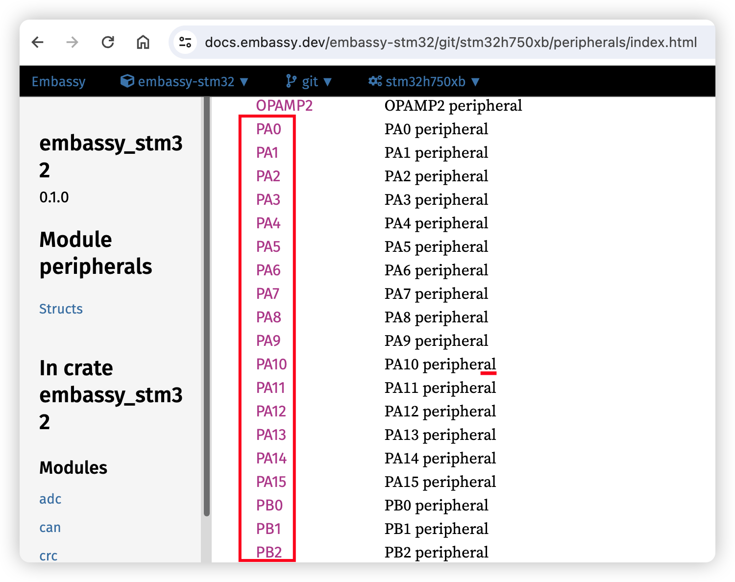
Finding Pin Names:
- Visit Embassy docs
- Navigate to your specific chip (e.g.,
embassy-stm32/stm32h750xb) - Check the peripherals module for valid GPIO pin names:
Matrix Type Configuration
RMK supports two matrix types:
Direct Pin Configuration
For keyboards where each switch connects directly to a GPIO pin (no matrix):
Direct Pin Behavior:
true(default): The pin is pulled high by default, pressing a key pulls it to lowfalse: The pin is pulled low by default, pressing a key pulls it to high- Use
"_"or"trns"for unused positions in the matrix
Vial Security Configuration - [security] Section
For enhanced security, Vial locks certain functions (like matrix testing) by default. You can set a key combination to unlock it.
Troubleshooting
Common Issues
Wrong GPIO Pin Names:
- Check embassy documentation for your specific chip
- Ensure pin names match exactly (case-sensitive)
- Verify pins support GPIO functionality
- Use correct format:
P0_00(nRF52),PIN_0(RP2040),PA0(STM32),GPIO0(ESP32) - For nRF52, some pins are behind a feature gate, for example
P0_09/P0_10are used as NFC pins by default. To use it as a normal pin in matrix, you should enable corresponding features(for example, nfc-pins-as-gpio) forembassy-nrfdependency.
Matrix Not Working:
- Verify diode direction in your schematic
- Check if you need
row2col = true - For local compilation with row2col, add the
row2colfeature to Cargo.toml
Direct Pins Not Working:
- Verify
matrix_type = "direct_pin"is set - Check
direct_pin_low_activesetting matches your hardware - Ensure unused positions use
"_"or"trns"